Any Unreal Engine Experts Here?

One thing I’m not sure about is when they speak of engine load when you are putting the project together, can I assume this load remains when the projected is converted into game status? Btw, I am oblivious (no surprise) to the transition from project to finished game that can be clicked on to launch. There are all these behind the scene nodes that dictate appearance in the game, Multiple materials and such, do all of these factors remain as is when the project is turned into a final project? Is there a step that converts the project into a game, and from the game, it can no lnger be taken apart in the same way as when it is being developed?

I'm not the best person to ask this question, since I've never made a game before, but my very general understanding is that while the editor does add some overhead to the performance deficit, your performance there will be reflected in when you compile it to a binary. There are some things that will be more efficient when you're running it by itself, like your code won't be in active debug mode, but performance hits from your shader stacks and whatnot will be the same in the editor as they are in the game itself.

Though with that said, having to worry about things like how many draw calls your various particles, materials, and shadowmaps are producing if you're really pushing the engine to its limit, and you probably won't have to get that into the weeds with it.

My impression which maybe in error that this is how height is handled when it come to blending textures, you don’t want it to be a 50-50 situation, and you want one to appear to have height, such as the tile so the moss can appear to growing in the grout between the tiles? I see this as a significant factor when trying to naturally blend say grasses with a Forest floor. Or maybe for the latter a scattering kind of blend which I’m working on figuring out how to do.

The weird thing about that is that it's using the heightmap to derive height, but it's kinda cheating it. It's acting more like a blend layer in Photoshop, pulling the darker areas of your height map image out first when you splat your paintbrush on your surface, rather than actually looking at it and calculating the height differences.

A good image editor equivalent to it would be to say that you're running a burn tool over your heightmap to produce the mask. It's not actually painting in the cracks, it's just coloring in the dark areas already there first, which happen to be your cracks.
 
Last edited:
The one thing that might help you the most is to break it down to it's most basic settings. In this case, the color/albedo textures. When you get right down to it, what' you're basically doing is repeating the same thing three or more times for each image that makes up a material.

Here's a shot of my material in UE, lerp only the three images in the albedo channel. If it looks like I'm covering old ground, or being condescending, don't be offended. I'm just trying to demystify the whole process as much as possible.

View attachment 9622

The nodes on the far left are probably the most mysterious. All they're doing is taking the UV map, and using a parameter to multiply it to shrink and grow the texture on your surface. This is good for those times when you grab a neat material you like, but it turns out it's out of scale with the rest of your stuff, giving you some HUGE ASS leaves or whatnot. 1 is UV x 1, or no change. 2 is UV x 2, or the texture repeated 2 by 2 times on the surface, 3 is UV x 3, or the texture repeated 3 by 3 times on your surface, and etc. etc.

The next stop on the noodle path is your image texture node (called Texture Sample in UE). In this case, your albedo. It's the texture that'll show up on your surfaces.

Further on down, you hit your lerp. This is where the magic happens. You want to blend two textures, your A and B. So you hook your nodes into socket A on the lerp, copy and paste them down below, add a new texture into your image texture node, and plug this new set of nodes into socket B.

Now you need a parameter to tell the engine how and where to blend these two nodes together. That's done by plugging a single color channel, in this case red, from the Vertex Color node into the alpha socket on the lerp node. This tells the engine that when you paint red in the vertex color channel, your 2nd texture will appear there. The topmost texture will go to the next undefined socket, which in this case is green. Now, when you paint red, you get your gravel, green will give you grass.

But you want that third texture, right? That's easy. Just lerp again. Copy one set of texture coordinates and image texture nodes, paste it down below, lead the Image Texture node to your 3rd texture, and hook your initial lerp to A, and your new texture to B onto another lerp. To define where it goes, take the blue color channel socket, and plug it the alpha on your 2nd lerp.

Why blue instead of green? Remember, the topmost texture defaults to the undefined color. I wanted green to be grass, so I made the 3rd texture blue.

Now, you can paint red, green, and blue on your surface to mix your grass, gravel, and dirt.

But what if you want to add in a roughness map, make your simple images more materially? Copy the image nodes and lerps above, and paste them down below your initial three. Change your textures so that the roughness image on A corresponds to the albedo on A, and so on and so on. You don't want to copy your Vertex Colors node, because you can just reuse it. Drag it down, and plug Red and Blue into the appropriate lerps.

But what about your texture coordinates? Well, you don't want your roughness map image to scale differently than its corresponding albedo. You'll want them to share the same size and space. To do that, just link your first texture coordinate nodes to the first set on your albedo and roughness, and repeat accordingly.

You'll end up with something like this:

View attachment 9623

For any other maps, just repeat the process, and plug the new lerps into their appropriate socket on the material node at the end.

View attachment 9624

So you can see what you're doing here. You're making a material out of three materials, and setting parameters to tell it how to blend the various parts of these materials together. Like I said, it's very simple, it just looks complicated because you're defining every little thing step by step by step.

Yeah, you probably gathered this from the videos you've watched, but I'm really wanting to hammer down the very basics here, to make triply sure you understand how this all works. Once you get the basics down, you can expand upon it, and start getting truly fancy.

The reason why I initially wanted to show you how to do things in Blender is because it's basically doing the same thing, but it's easier to follow, since it abstracts a lot of fiddly bits.
Just want to confirm the nodes on the left side of your material with red labels are texture coordinates? I'm going to construct this material and play with it along with the others I've made via tutorial to see what kind of results I get. I might even get brave and look at the forest scene tutorial material, but that is a reach for me at this point.

 
I'm not the best person to ask this question, since I've never made a game before, but my very general understanding is that while the editor does add some overhead to the performance deficit, your performance there will be reflected in when you compile it to a binary. There are some things that will be more efficient when you're running it by itself, like your code won't be in active debug mode, but performance hits from your shader stacks and whatnot will be the same in the editor as they are in the game itself.

Though with that said, having to worry about things like how many draw calls your various particles, materials, and shadowmaps are producing if you're really pushing the engine to its limit, and you probably won't have to get that into the weeds with it.


The weird thing about that is that it's using the heightmap to derive height, but it's kinda cheating it. It's acting more like a blend layer in Photoshop, pulling the darker areas of your height map image out first when you splat your paintbrush on your surface, rather than actually looking at it and calculating the height differences.

A good image editor equivalent to it would be to say that you're running a burn tool over your heightmap to produce the mask. It's not actually painting in the cracks, it's just coloring in the dark areas already there first, which happen to be your cracks.
That's one area where I have yet to venture, what turns a UE Project into a stand alone game...
 
Just want to confirm the nodes on the left side of your material with red labels are texture coordinates? I'm going to construct this material and play with it along with the others I've made via tutorial to see what kind of results I get. I might even get brave and look at the forest scene tutorial material, but that is a reach for me at this point.


Yup, it is indeed. I combined it with a multiply node to shrink and grow the texture on the surface.

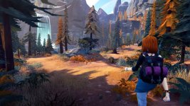
Here's what I'm working on, if you're interested. :D

Camper.jpg
 
Last edited:
Yup, it is indeed. I combined it with a multiply node to shrink and grow the texture on the surface.

Here's what I'm working on, if you're interested. :D

View attachment 9747
This art style reminds me of the Road 96 game art style. Is this for fun or work? Interesting material logic if that what I'm looking at. :unsure:

Road-96-Nintendo-Switch-3-1024x576.jpg
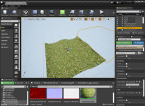
Tonight was a UE milestone, I actually sat down at my computer and worked on a project (Forest Scene) not attached to tutorial. It started slow, because with one of the materials I had, it would not vertex paint. Then I played with it a bit, did not change the material in any way, but it started to work. I think I remembered a step or keystroke/ Then I combined two materials I had, that blended two materials by adding height and cavity nodes to the one that did not have it when I started. Amazingly it still seems to function after I altered it. . Still looking at a way to blend 3 textures, with these other features, that's why I want to play with your material schematic.:)
 
Still looking at a way to blend 3 textures, with these other features, that's why I want to play with your material schematic.

Try this. You should be able to copy and paste it into the material editor like the forest material you posted earlier.

 
Try this. You should be able to copy and paste it into the material editor like the forest material you posted earlier.

Thanks! I’ll look at this.The question in my mind regarding how height works with 3 textures together, and it might be possible that it primary value of this kind of height is when use with something brick and moss (2 textures) where you want the moss in the cracks. When it comes to natural materials, just scattering it maybe good enough. This is a little different from elevation based height landscape blending that deals with things like layers up the side of a mountain.
 
Thanks! I’ll look at this.The question in my mind regarding how height works with 3 textures together, and it might be possible that it primary value of this kind of height is when use with something brick and moss (2 textures) where you want the moss in the cracks. When it comes to natural materials, just scattering it maybe good enough. This is a little different from elevation based height landscape blending that deals with things like layers up the side of a mountain.

If you're referring back to the Vertex Color tutorial from earlier, remember, it's not actually calculating height in this instance. Rather, it's using the blacks, greys, and whites of height map texture to assist the mask to fill in those lower parts before hitting the higher bits.

Though if you want to blend three heightmaps together, you can do that with an extra three textures, and another set of lerps.

As for totally random, natural settings, that technique can help with blends, since it'll make it so that you can set the grass texture to fill in the lower spaces of a gravel texture without having to put as much effort into it.
 
Try this. You should be able to copy and paste it into the material editor like the forest material you posted earlier.

Did you upload this to pastebin? If so thanks for the extra effort. I imported this material and put some texture into it, dirt, forest ground, and grass.

Remembering a previous blending tutorial that included height (masking) where the bottom texture (in that case tile) was considered primary, there were two textures (tile and grass) and the grass would fill in the grout part of the tile. And the author was always commenting the “primary” texture goes to the Lerp A pin. With multiple lerps in a chain, not always true, but for the last Lerp that connects to the Material node, primary or dominant texture would connect to the Lerp A pin, if that makes any sense.

So in this case there are 3 textures, no height/masking action (yet), and I wanted to keep the same hierarchy if that is possible, where the most dominant texture is the texture that is on the bottom, functioning as a base in the world. Ie, if you dig down, you cut the grass, and push aside the forest floor, to hit dirt.

Prioritized, that would be the bottom texture (dirt), with forest ground middle, and grass as the top texture (in the world). But in material structuring, as I have seen it displayed, based on how nodes/Lerps are strung together, in relationship with each other, the highest priority (primary) texture is listed on top. That is an organizational choice or preference.

So in the material structure, from top to bottom, it would be dirt, forest floor, and grass in the bottom. It has to do with blending mechanics based on a chosen material structure, and because I want the primary texture on top to mimic what I’ve seen before In previous tutorials and I like making organizational decisions based on a primary texture first,

I used the same relationship as in the previous 2 texture vector blending tutorial organizing the textures by heiarchy. So in the material below in each of the 3 groups base color (albedo), roughness, and normal, I stacked these 3 textures in each group from top to bottom as dirt (highest priority), forest ground (middle priority) and grass (bottom priority), prioritizing their values because as previously explained, in the world, I want dirt to be primary on the bottom, forest ground to be middle, and grass to be top. But to repeat myself, in the material the top priority goes on top, at least the way I am organizing the materials I’m making.
Not confusing right? Hey, I’m confused. 😝
I’m getting to my point… :)

So based on the hierarchy I created, when I drag this material to a mesh, what I first see is the dirt as the texture covering the mesh! Which is great because I’m considering the dirt to be the base. And based on how everything is connected, with 3 textures, grass should be the one that sits on top of the other two because of it’s height. In other words when grass grows, it will cover the other 2 And this is what is displayed,

So for painting controls:
  • With a freshly applied material, all you see is dirt whuch I have described as the primary texture or base. Forest ground and grass are in competition with each other above the dirt as follows:
  • R- paints forest ground over dirt, zero effect on grass.
  • R Shift- removes forest ground to reveal dirt, zero effect on grass.
  • B- paints grass.
  • B-Shift removes grass.
So far, so good. No I just need to see if I should or want to add more features. I’m comparing this to the Vertex Painting tutorial that has only 2 textures, but includes, UV, Spectral, Height, and World Displacement elements,


383B3BB3-1D7D-419C-B194-7CE9F16C6195.jpeg
 
Last edited:
So far, so good. No I just need to see if I should or want to add more features. I’m comparing this to the Vertex Painting tutorial that has only 2 textures, but includes, UV, Spectral, Height, and World Displacement elements,

Show off some screenshots of what you've made thus far. I'm interested in seeing them.
 
Ah, the joys of baking. One of these is 30,000 tris, the other is 2.

This could be you one day, Huntn. You just have to believe!

CurtainBake.jpg
 
Last edited:
Show off some screenshots of what you've made thus far. I'm interested in seeing them.
All I’ve made are texture tests so far experimenting. Last night I burned 3 hours working on it. It’s a handful understanding material mechanics and experimenting with nodes. When I have something worthy I’ll post it,

Pretty soon I’ll be tackling the infamous blender mesh for the Forest scene. Still deciding on if I like that material of yours or to expand on it’s capabilities, But I’m also considering expanding on that scene, I might just curve the road off to the side where the camera is located If that is not too hard,

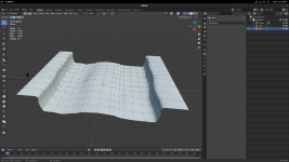
Do you remember the mesh with the raised center portion? :)

52B65EAF-B546-490B-A6D5-C4CC6B6BDB41.png
I’m assuming to make this curve to the left at the end close to the camera. you could just grab a series of vertices and start pulling them left? It might take a segment devoted just to this.
 
Here is a good example of me wasting an evening. I made this static mesh in blender, 2 parts a center and a side. It looked like the image in the previous post. So I imported them into UE, fox file format, the center one comes in looking normal with the gray checker pattern on it. But the side comes in as just an outline. You can see the outline on the right in the image below. Well I'll just apply a texture or a material to it. Nope it wil not accept any of that. I double checked the texture settings to see if there are any obvious differences in these two files and I can't find any. Any idea? I've also asked this over at the UE forums, and one guy has been helpful there so maybe I'll get an answer by tomorrow. This virtually stopped me in my tracks as I dickered with trying to figure this out...

Import Issue.PNG
 
I’m assuming to make this curve to the left at the end close to the camera. you could just grab a series of vertices and start pulling them left? It might take a segment devoted just to this.

What I did when I made that mesh was grab the outermost edge on that side, extruded it up, then ran a second extrude, and pulled it out. After that, I ran a couple of loop cuts, and doctored it up a bit to make it lumpy.

Pretty soon I’ll be tackling the infamous blender mesh for the Forest scene. Still deciding on if I like that material of yours or to expand on it’s capabilities, But I’m also considering expanding on that scene, I might just curve the road off to the side where the camera is located If that is not too hard,

It's a simple material, pretty straightforward. It provides the basics, which can be expanded upon easily.

Curving the road? There's a number of different ways you can do that. One, you can model it by hand, which is the most obvious solution to it. But you can also get fancy, and array your road piece along a curve. That's what I did with my train tracks in my last project. You can do this in both Blender and Unreal, though, par for the course, I'm not 100% sure how to do it in the latter.


This virtually stopped me in my tracks as I dickered with trying to figure this out...

If I had take a stab at a guess, I'd say your normals are flipped on the wrong side. If you move the camera underneath the mesh, you can see the surface there right? If so, do this...

 
What I did when I made that mesh was grab the outermost edge on that side, extruded it up, then ran a second extrude, and pulled it out. After that, I ran a couple of loop cuts, and doctored it up a bit to make it lumpy.


It's a simple material, pretty straightforward. It provides the basics, which can be expanded upon easily.

Curving the road? There's a number of different ways you can do that. One, you can model it by hand, which is the most obvious solution to it. But you can also get fancy, and array your road piece along a curve. That's what I did with my train tracks in my last project. You can do this in both Blender and Unreal, though, par for the course, I'm not 100% sure how to do it in the latter.


If I had take a stab at a guess, I'd say your normals are flipped on the wrong side. If you move the camera underneath the mesh, you can see the surface there right? If so, do this...


Thank you! Yep texture on the bottom side. Normals were flipped for one of the meshes. I looked this up for Unreal Engine how to flip normals and the answer eluded me. I went back to Blender, checked the mesh, and under maybe coordinates(?) one of them was -1 while the other two were 1.0. Simple changing the -1 to 1 fixed the issue.

As far as the curve in the road, I just don’t like the idea of the road running into the camera. It looks fine for an image, or a painting, but the way it was made, everything behind the camera is unfinished. I want it to be finished all around and a road that curves and dissapears around terrain seems better if I can do that.

I’m going back into Blended and see if I can make that happen. An issue I think is the way I made the road. Where as, you made the road and elevated sides as one piece, I did as the tutorial did with 3 pieces, a bottom central piece of road and two elevated sides, separate that butt into the center road portion.

I think ultimately I want the outside of most of the road pieces to remain square so they can be tiled to give the road length receding from the camera. But closest to the camera where I want to make the road curve, I could take a segment composed of the 3 pieces, two sides and the center, some how merge them so when I start dragging a curve into the road part, the vertical sides that define the road area, will be dragged along. Maybe I could do this in just one segment, or maybe it will take 2. I’ll have to see how tight I can make this curve.
 
I’ll have to see how tight I can make this curve.

The nicest thing about working with 3D is that you don't have to stick to straight square tiles. When you get your tile to follow a curve, it'll deform the underlying geometry to conform to the curve you've tied it to, allowing you to do all kinds of cool stuff.

It allows you to do things like, say, make a fence that twists along the edge of the road without having to design the whole thing by hand. So long as the mesh has enough geometry to deform properly, it'll look completely natural.

For example...


Road.jpg


Then you can fill in the outside edges with free floating geo that crosses with your road geometry.
 
The nicest thing about working with 3D is that you don't have to stick to straight square tiles. When you get your tile to follow a curve, it'll deform the underlying geometry to conform to the curve you've tied it to, allowing you to do all kinds of cool stuff.

It allows you to do things like, say, make a fence that twists along the edge of the road without having to design the whole thing by hand. So long as the mesh has enough geometry to deform properly, it'll look completely natural.

For example...


View attachment 9824

Then you can fill in the outside edges with free floating geo that crosses with your road geometry.
Holy crap, did you do this from the mesh you made?? Looking forward to your tutorial! :D
See I have some preconceptions that are wrong, such as keeping meshes confirming to the grid. I had no clue you could make a serpentine shape like this and then easily mesh it with the rest of the world.
 
Holy crap, did you do this from the mesh you made?? Looking forward to your tutorial! :D
See I have some preconceptions that are wrong, such as keeping meshes confirming to the grid. I had no clue you could make a serpentine shape like this and then easily mesh it with the rest of the world.

I'll do a quick one for you right fast.

Like I said, the grid is primarily there to act as a measuring guide. For objects that are meant to tile, like modular modeling, you'll want to stick to the grid for simplicity sake, but for the most part, you can use it or ignore it at your own discretion.

What I usually do is just slap my geometry into a scene, and start working at it. Once I'm done, I'll compare to some shape that has a specific size, and scale it up or down accordingly. This isn't CAD or architectural work. You don't have to be exactingly exact down to the barest millimeter. Your primary concern is that it's all sized realistically enough to look natural, and all your various parts gel well together.
 
Tutorial! :D

Okay, here's a very slow and plodding tutorial, just for you! If you're wondering what I did near the start of the curving, I flatted the bezier curve to make the initial two nodes aligned, because by default, Blender gives you this weird bend on their beziers that will mess you up if you're aligning big objects.

 
Back
Top